
Cellular Manufacturing and U-Shapped Cells
Flexible cells (cellular manufacturing) represent the most advanced type of plant layout. They are based on flow or product-oriented layouts, trying to eliminate all waste (activities that do not add value) and it is able to provide the necessary flexibility in terms of diversity in products and production volumes that is present in the process-oriented layouts.
For this type of layout, it will be required that the operators have polyvalent training, since an operator will be in charge of different operations in the same process, so that they should not wait for the machines or equipment of the different stations to finish, but simply go to the next operation. The objective is to minimize at the maximum level the waiting time (non-productive time = waste) that the worker has. This means that while a machine is working in a part, the operator will go to the machine at the next station.
The most usual layout in Cellular Manufacturing: U-Shaped Production Cells
Let's imagine a process consisting of 4 tasks:
- Bending
- Stamping
- Spot Welding
- Screwing
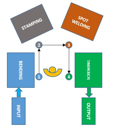
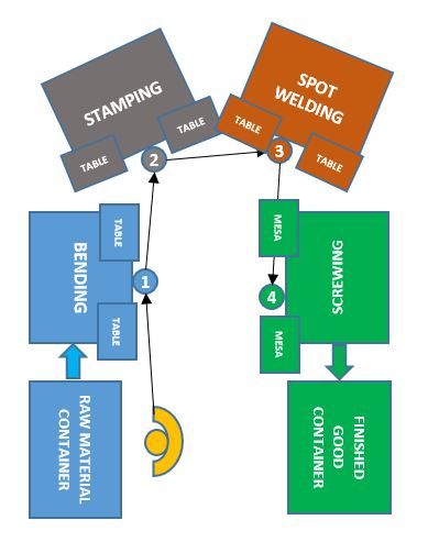
If we implement this product-oriented process with a polyvalent worker for the 4 stations, it would look like this:

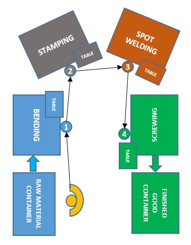
As it can be seen, this layout is much more optimal than if it were a process-oriented one; however, it has the drawback that it will be difficult to coordinate the input and output of material. To improve this, the islet must be opened so that the flow of materials is facilitated as shown in the image below.
The semi-automatic machines with automatic loading and unloading in the U-shaped cells
In order to make the U-shaped cells as efficient as possible, semi-automatic machines should be used, that is, with an operator required for their operation. This will make the investment less than fully automating, which will allow it to adapt to market demand more easily, correctly amortizing the investment. It may happen that the commercial department foresees a large number of sales and that it intends to automate everything, however, if the sales are not as expected, that great investment will not be amortized with the volume of product. Having mentioned this risk, it's worth to say that semi-automatic machines will give us that flexibility needed.
An important feature of these machines should be the automatic loading and/or unloading of parts, in order to avoid double handling by the operator. We are going to explain this through the previous example, first without automatic unloading and then with automatic unloading in the machines.
Suppose that the line is in operation and that a production cycle has already been completed, therefore there is already a material that has been bent, another stamped, another spot welded and finally another screwed, and the operator is at the point where the raw material is picked up to start the process over again with the bending station.
Machines without automatic unloading
Suppose there is a table to the left of each station, where the product pending to go through the station is placed, and another to the right of the station, on which the product that has already been processed by the machine will be placed.
We are going to briefly describe the sequence of operations in the case of having machines without automatic unloading, so the mentioned unloading task must be carried out by the operator:
1. Take material from the raw material container and move to the bending station.
2. Put the material on a table near the bending station.
3. Take the material out of the bending machine and place it on the table close to the bending station.
4. Take the material placed in step 2, feed the bending station and start the machine.
5. Take the material plasced in step 3 and move to the stamping station.
6. Leave the material on a table near the stamping station.
7. Take the material out of the stamping machine and place it on the table near the stamping station.
8. Take the material placed in step 6, feed the stamping station and start the machine.
9. Take the material placed in step 7 and move to the spot welding station.
10. Leave the material on a table near the spot welding station.
11. Take the material out of the spot welding machine and place it on the table near the spot welding station.
12. Take the material placed in step 10, feed the welding station and start the machine.
13. Pick up the material placed in step 11 and move to the screwing station.
14. Leave the material on a table near the screwing station.
15. Take the material out of the screwing machine and place it on the table near the screwing station.
16. Take the material placed in step 14, feed the screwing station and start the machine.
17. Take the material placed in step 15 and move it to the finished part container.
Machines with automatic unloading
Now let's see if the unloading was done automatically (Chaku-Chaku system) on the table on the right of each station, so that the operator who carries a part coming from the previous station would have a space to place it in the machine and activate it. The goal is to achieve a "one piece flow" avoiding double manipulations:
1. Take material from the raw material container and move to the bending station.
2. Leave the material, feed the bending station and start the machine.
3. Pick up the material ejected automatically from the bending machine and place it in the stamping station and start the machine.
4. Take the material ejected automatically from the stamping machine and place it in the welding station and start the machine.
5. Pick up the material ejected automatically from the welding machine and place it in the screwing station and start the machine.
6. Take the material ejected automatically from the screwing machine and place it in the finished part container.
In this way, you can clearly see the savings in movements that the fact of having an automatic unloading means, which will allow us to improve manufacturing leadtime, and therefore the number of orders that we fulfill for our customers.Cycle time will also improve, making it considerably cheaper to manufacture the product. In the end, EVERYTHING is about using time efficiently and productively.
Examples of how to carry out the loading/unloading of parts automatically
Some examples that I have seen based on my experience would be the following:
- Robot with a "claw" or "hook" performs loading and unloading of material as shown in the image. When the machine finishes the cycle, the robot removes the part from the work position and places it on table 2, and when the operator has placed the part pending to be processed on table 1 and activates the machine, the robot moves the part of table 1 to the machine work position to start the cycle.

- Unloading system with horizontal-vertical movement and loading with horizontal movement: When the machine finishes the cycle, the finished part is automatically ejected with a horizontal movement (in the Y axis), to be later picked up by a system that moves the part to a vertical position (in Z axis). In this way, the position to feed the machine remains free, so when the operator places the part in the machin and activates it, it will only move on the Y axis to the working position, as shown in the figure and start the cycle.

- Ejection of the part by gravity: in this way the machine ejects the part that falls by gravity to a buffer located below the working position of the machine, leaving free space in the working position for the next part.

There are more systems and many to design depending on the specifications of the product or the line, but the objective is always to think creatively to avoid this double manipulation.
The flexibility offered by U-shaped cells
Here we are going to show with an example how easily U-shaped cells production rates can be adapted to different volumes, introducing or removing workers from the line to cope with the customer's Takt Time.
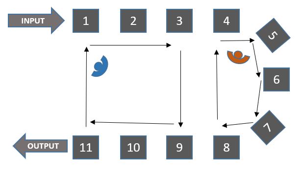
Let's imagine that our customer gives us a project to manufacture 6000 units/week, which means a Takt Time of 52 units/hour. In the process design, to obtain that Takt Time, 11 stations and 3 operators are needed, distributed as follows in a balanced way:
- Operator 1 performs operations 1, 2, 10, 11.
- Operator 2 performs operations 3, 4, 8, 9.
- Operator 3 performs operations 5, 6, 7.

However, the market does not respond as expected, and our customer tells us that they only require 4,000 units/week, assuming a Takt Time of 35 units/hour. After making calculations, we see that we can adapt the line to manufacture with 2 operators in a balanced way, demonstrating the flexibility of the U-shaped cell to adapt to customer demand without problems, avoiding cost overruns and waste. The distribution of tasks would look like this:
- Operator 1 performs operations 1, 2, 3, 9, 10, 11.
- Operator 2 performs operations 4, 5, 6, 7, 8.
The Nagare Method or Rabbit Run
In the event that there are difficulties when balancing the line and reassigning tasks, we can apply the "Nagare", "Rabbit Run" or "Rabbit Hunt" method, which consists of a worker taking charge of all the stations of the process, but next to it, with the necessary space so as not to disturb, the necessary operators will also be there to comply with the required cycle time. The required operators will be circling the entire U with almost perfect balance (because from time to time there may be queues waiting for a certain station to finish).
Below you can see how this method would be for the 3 operators. Each one of them will carry out the complete process going from station 1 to station 11.

In this arrangement, sometimes it is difficult for the operators to coordinate to leave the spaces and avoid the queues (as mentioned above) but with adequate training this coordination is achieved.
Wastes eliminated with the U-cells implementation
The U-shapped cells allow us to minimize the following wastes:
- Motion: by assigning tasks around the workers, reducing the number of steps they must take, in addition to the application of automatic unloading to avoid double manipulation.
- Motion: by having the input and output of the material much closer than in a linear layout.
- Transport: by having the operations very close to each other in a linear flow.
- Stock: the WIP (Work-In-Processs) is eliminated by balancing the cycle of each work station operating with one-piece-flow.
- Quality: it is improved because the one piece flow allows quality control unit by unit in each station.
Another layout for Cellular Manufacturing: S-Shaped Flexible Cells
Another type of cellular layout that we can find are S-shaped cells that are very useful in the case of very long lines to avoid having a very long building and favor internal logistics of materials. It is very common to see this type of layout in car assembly factories.
It would be something very similar to several cells in a U joined as seen in the image below.

L-Shaped Flexible Cells
This layout is normally used when there is no space to implement a U or S due to the circumstances of the plant, since it does not have all the benefits that they have.