
The Importance of Initial Process Design based on SMED in Multiproduct Lines
Why is SMED key in the initial design of multi-product production lines?
SMED (see Introduction to SMED: quick changeover) is used for quick tooling changes and it is crucial to apply it in the initial process design stages of multi-product assembly lines for several reasons:
- Optimisation of production flexibility from line conception: Designing the assembly line with SMED in mind ensures the flexibility of the line and it is born with the capability for quick changeovers and adjustments.
- Reducing the number of additional future investments: Designing the line from the start using SMED principles avoids the need for later modifications or adjustments, which can involve high re-engineering costs or equipment upgrades.
- Creating changeover standards from the start: Standardising changeovers from the initial process design creates an environment where changeover times are predictable and consistent, making production planning and scheduling easier.
- Maximising OEE: Designing equipment and processes with short changeover times will improve the line's OEE indicator.
- Space optimisation: Incorporating SMED from the start allows the production line design to be more compact and efficient.
Ideas on decisions on how to carry out the initial process design to reduce changeover times between products
Here are some ideas on key decisions that can be made in the initial process design to reduce switching times between products:
Modular design of equipment
This consists of designing machines and workstations with modular components that can be easily interchanged.
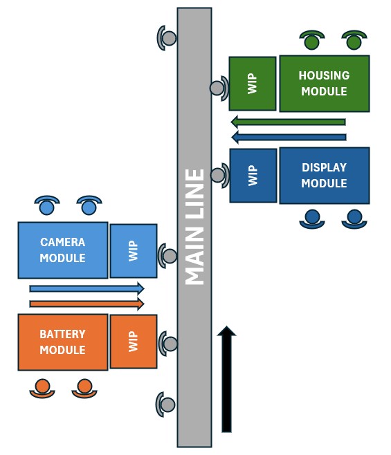
For example, imagine a mobile phone assembly line that has the following components in modules (separate stations) for later assembly on the main line:
- Display module: Displays are assembled in a separate station, where different types of displays (LCD, OLED, or different sizes) are pre-assembled. Subsequently, the display module is integrated into the body of the phone on the main line.
- Battery module: Batteries are assembled and tested separately in a dedicated station and depending on the phone model, different sizes or types of batteries can be easily interchanged during final assembly.
- Camera module: The cameras of the phones, which can differ in qualities, single, multiple..., are assembled as separate modules and then integrated into the phone at a later stage.
- Housing module: Phone housings, which may vary in colour, material (plastic, metal, glass) or size, are also assembled as separate modules and integrated into the final phone depending on the model.
The 4 modules mentioned above will feed a WIP that will be used in the main line. In this way, by decoupling these module stations, the main line will not stop due to reference changes (it will have modules mounted on the WIP) or will do so much less than if everything was assembled in line.
As can be seen from the SMED point of view it brings:
- In SMED, one of the keys is to separate internal activities (which require stopping the machine) from external activities (which can be performed while the machine is still operating). The modular design allows much of the setup work (assembly and testing of modules) to be done at external stations outside the main line. In this way, when changeover is necessary, only the final assembly is performed on the production line, which is fast and efficient.
- Flexibility: By making it possible to produce different handset models on the same main line, adapting to the customisation requested by the market, without losing efficiency on the line.
- Reduced changeover times: With the modular design, long machine adjustment times are avoided, which would mean changing multiple references given the customisation demanded by the market.
- Better quality: the modules are tested before being transported to the main line, ensuring that only OK parts reach the main line.
Standardising tooling and components
Designing the production line from the start with standardised tooling and components eliminates changeover complexity and reduces downtime between models.
Take for example a washing machine production line with three models of washing machines. If different screws, fasteners etc. were used, this would mean feeding the line with each screw reference at each changeover and/or changing the tooling for tightening. It is therefore important to standardise both tools and components. In this case, by standardising from the product design and production line to use the same screws, fasteners and tools, it will save a lot of time in the change of reference.
Use of quick-connect systems
This can be seen for example in plastic injection moulds. Normally, changing a mould requires a lengthy process of disassembly, adjustment and manual alignment of the components. However, quick-connect systems, such as magnetic mould clamping systems, are incorporated. This system uses powerful magnets to hold the mould to the press without the need for screws or mechanical fasteners. These magnets are activated automatically when the mould is positioned, eliminating the need to manually align and fasten the mould with screws to the mould plate. This process takes seconds, compared to the approximately 30 minutes it would take to attach it manually. The mould should be designed from the outset to be attached to a magnetic plate, so it is important to take this into account from the initial design.
Also in the world of plastic injection moulding we can find quick connect systems, where operators can prepare the cooling hoses (which carry water for cooling) for the next mould externally before stopping the machine, making the changeover much quicker and more efficient. This also has to be conceptualised into the mould from its initial design.
Tools and tooling close to the workstations
Tools and tooling should be close to the workstation: operators should be prevented from walking to different areas to collect tools and tooling at changeover time. A storage system or mobile tool trolley can be located close to the workstation. In this way, when changing tools, operators do not need to leave their workstation.
Adjustment and calibration automation
Automation technologies should be incorporated to allow automatic adjustment of machine and line configurations according to the product to be manufactured. This reduces or eliminates manual intervention during changeovers, guaranteeing accuracy and speed in the adjustments.
As an example, let's assume a bottle production line with 3 sizes (A, B and C). At the moment of changing from manufacturing A, to manufacturing B, with the reference change information entered by the operator, the filling and labelling machines will automatically adjust height, speed, position of filling heads, labelling, etc. As can be seen, these adjustments are made without manual intervention, avoiding human error when entering machine parameters.
Visualisation and signposting of the changeover process
The initial process design should include clear visualisation and signage systems to guide operators during production changeovers to make them more efficient. This involves:
- Use of visual panels to show machine status and changeover progress.
- Indicator lights or turrets that signal when an adjustment has been completed or if there are problems.
- Clear labels and markings on tools and stations to reduce search time.
- Warning systems to alert if changeover steps are not performed correctly.
For example, following on from the previous example of bottle making, let's imagine that we do not have the automatic technology mentioned above (which would be ideal). Coloured lights can then be installed to indicate which parts of the line require adjustment. In addition to this, digital displays could be used to show the steps to be followed to facilitate the changeover process.
Flexible layout design
It is important that the initial process design allows for easy movement of equipment and materials, with well-defined routes and spaces reserved for quick changeovers. This facilitates the reconfiguration of the workflow according to the product, avoiding long relocation times of machines or tools.
In this sense, dynamic racks are a key tool. These racks allow quick and efficient access to the necessary tools and materials, facilitating organisation and minimising search time. By using shelving that adapts to the workflow, the layout of the elements is optimised, which not only improves productivity, but also contributes to better ergonomics and safety in the working environment. In this way, live shelving plays a fundamental role in the agility and efficiency of the tool change or adjustment process, aligning with the principles of continuous improvement promoted by SMED (See post Productivity and Order: Dynamic Shelving for Lean Manufacturing).
Case example: Workstations designed for fast changeovers
Let's imagine a production process consisting of 4 workstations with 4 operators, which has a layout as shown below. In this line it is planned to manufacture 16 references, and there will be three production batches per week of each one of them, so 3 x 16 = 48 reference changes will be carried out.
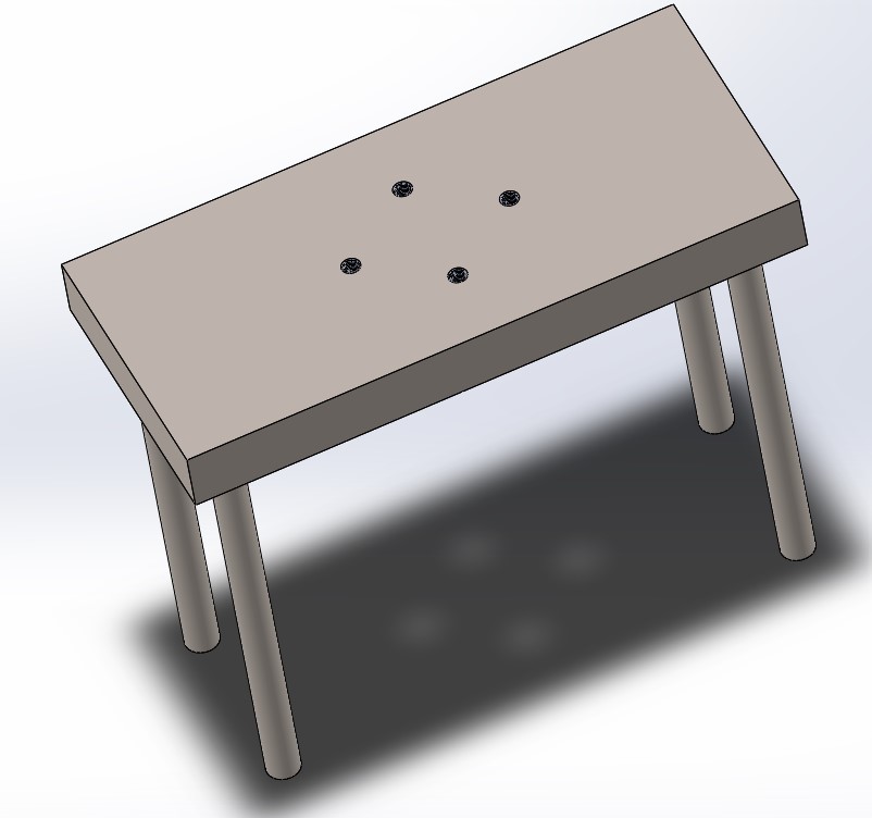
To change the reference, the operators must change the support that is anchored to the table with 4 screws. Let's see how the worktable would look like:
- This would be the worktable with 4 holes to place the screws.
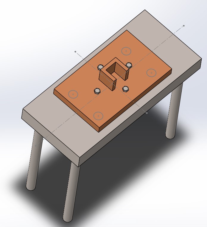
- This would be the support with the shape of the workpiece to be screwed to the worktable.

- Here we would have the complete assembly with the 4 screws.
To simplify the problem, let's assume that in the replacement process each operator takes the same amount of time and performs the following operations:
- Take tool to unscrew old reference support (10 seconds).
- Remove the 4 screws with the help of the tool (10 seconds each unscrewing x 4 = 40 seconds).
- Remove the old reference support and transport it to a nearby warehouse (60 seconds).
- Takes the new reference support and transports it to the production line (60 sec.)
- Places support on work table and faces it to position the first screw (60 seconds)
- Turns support to position the second screw (with this screw the other two will be positioned - 30 seconds)
- Insert screws 3 and 4 to fix the bracket completely (10 seconds each screwing x 2 = 20 seconds)
- Set the parameters in the machine corresponding to the new reference, with the help of a book that indicates which parameter to use for each reference (90 seconds)
Let's assume that this is the only change carried out by the operator and it has cost as we can see 10 + 40 + 60 + 60 + 60 + 60 + 60 + 30 + 20 + 90 = 370 seconds each change. If 48 changes are made, we will have that 48 x 370 = 17760 seconds are lost in reference changes, or 296 minutes.
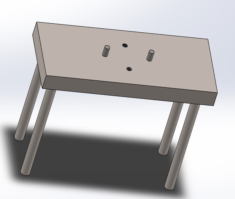
Now let's assume that the workstation has been designed with two things in mind:
- The stand has two positioners that restrict movement and guide the operator to anchor it to the table with only two screws.
- A software has been acquired that allows to load the machine parameterization only by entering the reference, avoiding having to enter it manually.
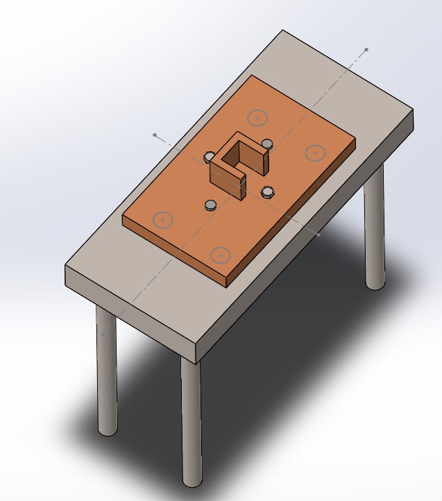
In this case we would have the following:
- Work table
- Full assembly
We will now have the following times:
- Take tool to unscrew support old reference (10 seconds).
- Remove the 2 screws with the help of the tool (10 seconds each unscrewing x 2 = 20 seconds).
- Remove the old reference support and transport it to a nearby warehouse (60 seconds).
- Takes the new reference support and transports it to the production line (60 sec.)
- Places support on work table and with the help of the positioners places it quickly (20 seconds)
- Places screws 1 and 2 to fix the support completely (10 seconds each screwing x 2 = 20 seconds)
- Load the parameters by entering the new reference (10 seconds)
If we examine the changeover time now, we see 10 + 20 + 20 + 60 + 60 + 60 + 20 + 20 + 20 + 10 = 200 seconds each changeover. If 48 changes are made, we will have 48 x 200 = 9600 seconds lost in reference changes, or 160 minutes.
That is, with this initial design alone, we will have 296 - 160 = 136 more minutes of line availability per week, which is 2.27 hours. If we assume that a year's manufacturing is 47 weeks (taking into account vacations and so on), we will have 2.27 x 47 = 106.69 more available manufacturing hours, which is 4.44 days.
If we convert the “saved” hours to money, taking into account that in Spain it is 25 euros/hour, having 4 operators, we would save 25 x 4 x 106.69 = 10669 euros, which would justify the investment in a software to speed up the change of reference.
It can be seen then a very important saving of time (and money) by a simple more efficient design and a small investment in automating the entry of parameters by reference.
Conclusions: Design with SMED in mind, an advantage in multi-product manufacturing
In summary, designing the process upstream with SMED in mind not only optimizes changeover times and operational efficiency, but also generates significant economic impact by reducing downtime and improving productivity, resulting in considerable savings over time.